Automated visual inspection for precision components
We build inspection stations that catch surface and dimensional defects on drill bits, nuts and bolts, at line speed, on the factory floor.
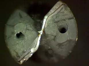
- ACoolant hole
- BPitting at the coolant hole
- CChisel edge
- DDamaged cutting lip
What we inspect
Cracks, chips, burrs, grinding marks, plating defects and thread damage on small precision parts, plus key dimensions measured from a calibrated backlit view. We focus on the checks your team still does by eye.
Drill bits
Cutting edges, margins and flutes
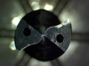
Worn drill bit under a 100X microscope. What we look for
- Chipped cutting edge
- Worn or rounded margin
- Flute damage and chip packing
- Bent shank
- Coating loss and burn discolouration
- Incorrect point geometry
Nuts
Internal threads, faces and corners
Outline drawing of a hex nut seen from above, showing the internal thread and across-flats dimensionDrawing. Photograph to follow. What we look for
- Deformed internal thread
- Cross-threading
- Burr on the bearing face
- Out-of-round body
- Incomplete forming
- Cracks at the corners
Bolts
Thread form, heads and plating
Outline drawing of a hex head bolt in side view, showing the head, shank and thread formDrawing. Photograph to follow. What we look for
- Flattened thread crest
- Incomplete thread run-out
- Malformed head or bad stamping
- Bent shank
- Chamfer and point damage
- Cracks at the head-to-shank fillet
- Missing or scratched plating
How it works on your line
A camera, lighting and a fixture at the inspection point. An industrial computer runs the models locally, with no cloud dependency. A pass or fail signal goes to your PLC for rejection or alarm, and every part is logged with its image.
How we workStep 1
Camera, lighting and fixture
The part is presented the same way every time. Fixed lighting and a fixture at the inspection point matter more than the camera: they are what make one part comparable to the next.
Step 2
An industrial computer at the line
The models run on a computer in your plant. Nothing is sent to a cloud service, so the station keeps working when the connection does not, and your part images stay with you.
Step 3
A pass or fail signal to your PLC
The station gives your PLC a signal it can act on, for rejection or for an alarm. How you use it is your decision, and it is wired to your existing control scheme.
Step 4
Every part logged with its image
Each inspected part is recorded with the image it was judged on. When a call is questioned, there is something to go back and look at.
How we start: a paid four week pilot
Week 1
Scoping
- We agree which parts and which defects are in scope.
- You give us defect samples, including the ones you currently argue about.
- We write down the success criteria together, before any model exists.
Week 2
Optics and image capture
- Lighting trials at your line, on your parts.
- We fix the camera position and the fixture.
- Image capture begins once the view is stable.
Week 3
Model build
- We build the model on the images captured at your line.
- Where a dimension matters, measurement is added alongside the defect check.
Week 4
Shadow run
- The station runs beside your inspectors, judging the same parts they do.
- Disagreements are collected and reviewed rather than explained away.
What you receive
At the end you receive a report.
- Recall, measured on your own parts
- False reject rate, measured on your own parts
- Cycle time, measured on your own parts
A clear go or no-go recommendation, including when the answer is no.
The pilot fee is credited against a production system.
Where we are today
Kalyan Labs is early. We are running pilots and we do not claim a large installed base.
We will tell you plainly whether your defect is one we can catch, and we share the measured results of every pilot with the customer who paid for it.